Raptor Innovation Summit 2026 — Registration is Live
How Do I Configure My Software to Use Wake-ON-CAN or Wake-ON-LIN?
Normally Raptor™ Electronic Control Units (ECUs) support the capability of awakening in response to a voltage on the ignition or wake line, typically identified as ‘WAKE_INPUT1’ on the datasheet. Additionally, some Raptor ECUs support the capability to configure the unit to wake on another environmental stimulus such as an incoming CAN message, or a change on the LIN bus. This capability can be used in many application situations, such as to wake up internal controllers when the vehicle door is opened. This Power User Tip provides an overview of configuring the software to accommodate these scenarios.
Along with this Power User Tip, we have prepared a sample model so you can follow along.
You may download it here.
Setting the Wake Source
For this example, we will be enabling Wake-On-CAN for CAN3 on this ECU. To configure the ECU to awaken based on messaging on CAN3, we implement an App Trigger set to execute on Startup. Inside that subsystem, we use the ‘Set Hardware Option’ block to configure the WAKE_SOURCE for the ECU.
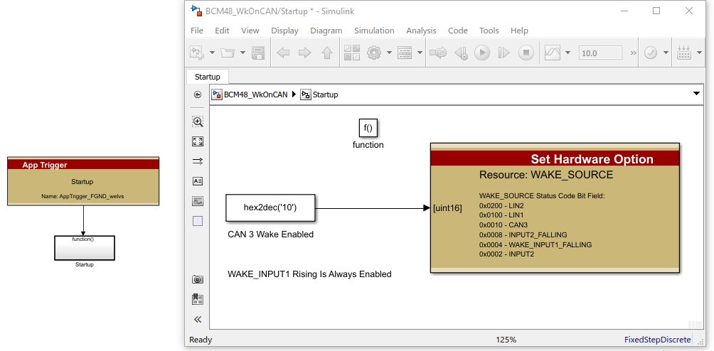
This configuration change will take effect after the first power-up after programming. The ECU will need to be awakened via WAKE_INPUT1 (Ignition) to be available for programming. This input is always enabled for waking the ECU regardless of what other sources you may have configured.
Reading the Source of Wake
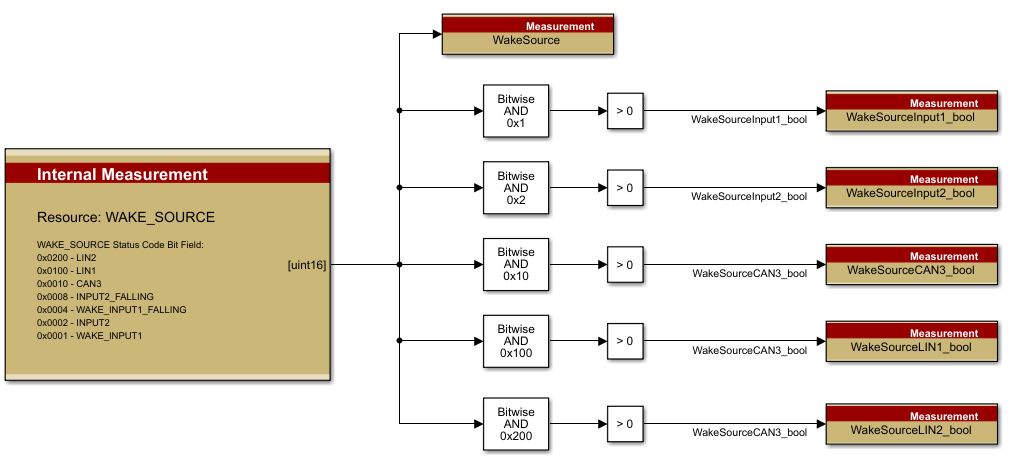
Typically an application will want to determine the wake source or reason that it was awakened. In the normal case where the ECU is only able to be awakened via the WAKE_INPUT1 (Ignition) input this is often simply implied because in that case there is only one way to wake the ECU. In cases where there are multiple wake sources available, the application may need to use different logic for keeping the ECU awake based on which source is responsible for the wake up. To read the WAKE_SOURCE, you can use an ‘Internal Measurement’ block as shown below.
Controlling ECU Shutdown
Network Management
When utilizing a communication-based wake source (CAN/LIN) there must not be any bus traffic on the wake source. On many systems, this network management determines when the modules go to sleep through a messaging protocol. If your controller is the master, you will need to tell other devices when to shut off their broadcasting and go to sleep. If your module is not the network master, you will need to honor network management as a slave and allow the other modules to go to sleep by shutting off broadcast. An alternative to a protocol based network management would be to shut off the power from all other ECUs to ensure they stop broadcasting.
Shutdown Timing
In a basic standard operating scenario where the ECU is waking based on an ignition line, the ECU will stay awake as long as the ignition line stays high. When the line goes low the ECU will typically tidy up, store Nonvolatile Memory, and then go to sleep. In the case of Wake-On-CAN, the logic needs to be a little more complex. CAN messages arrive at various intervals. Assume a single message on the CAN bus being sent at a 500 ms rate. That is likely enough time for the ECU to wake, store Nonvolatile Memory, and go back to sleep. You would not want to wake, store and sleep every 500 ms as you would quickly wear out the storage memory. More likely, you would want to Wake-On-CAN and stay awake as long as you see messaging, perhaps sleeping after messaging stops for 10 seconds.
In order to implement that, you could implement a timer that counts up every Foreground execution.
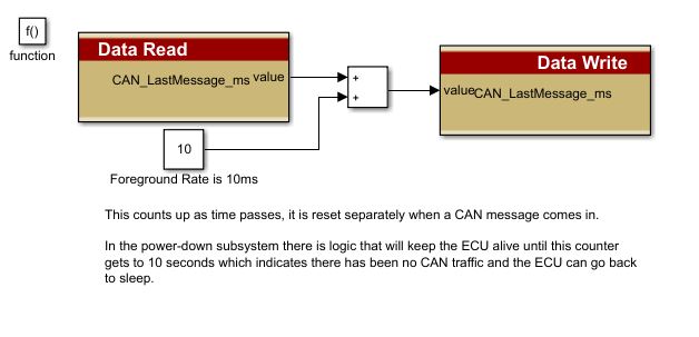
Then whenever you see the message you need (in this case we are looking for 0x4000 extended specifically), you would reset the counter.
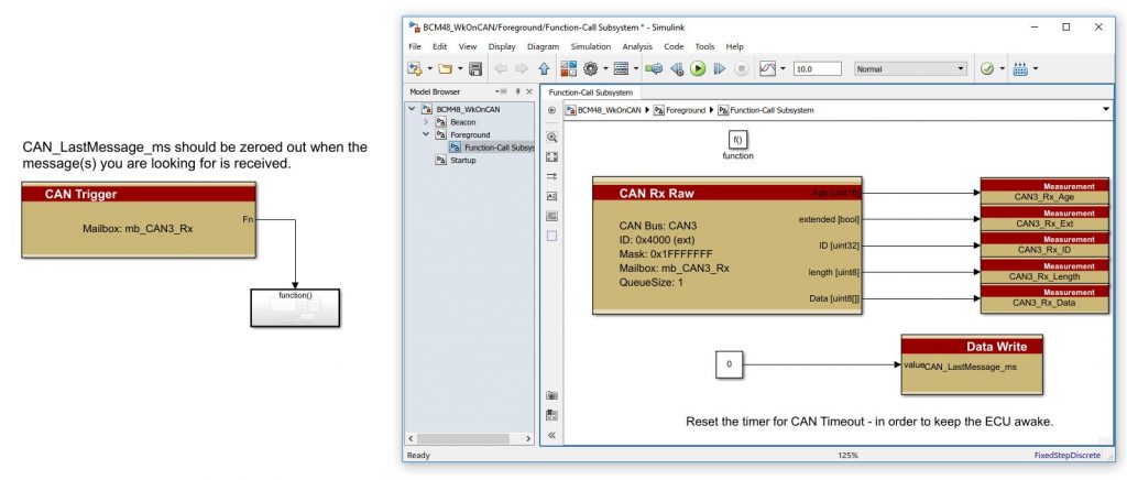
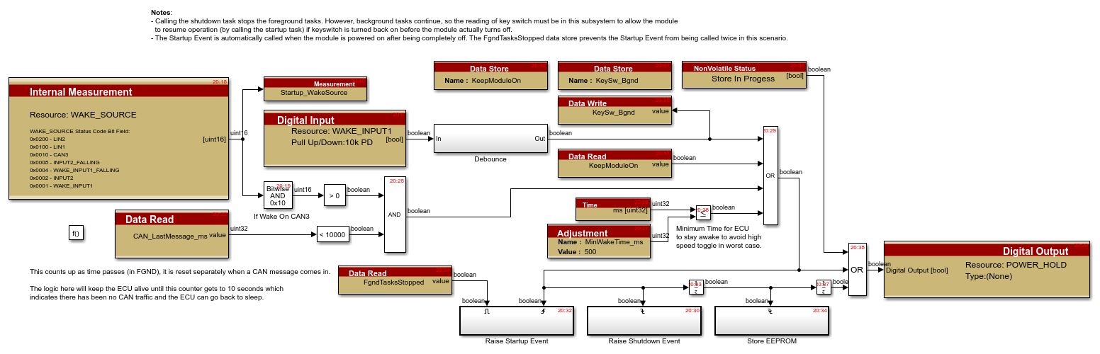
Then, in the power-down subsystem where the ECU power control is implemented, you can determine the wake reason and use the timer to keep the ECU awake as long as messaging is coming in every 10 seconds.
Here we have implemented updates to keep the ECU alive based on either the WAKE_INPUT1 source or in the case of a Wake-On-CAN for 10 seconds after the last expected CAN message (ID 0x4000 extended).
The sample model provided gives an example of an implementation for developing a Wake-ON-CAN solution for Raptor ECUs. For any questions or concerns, please New Eagle’s Support page.
Bonus Tip on GCM-5605B-048-1906:
This module has a hardware-based wake source that doesn’t have any software configuration to select the wake source. It will wake from the key switch, CAN2 or LIN2. This means any of these sources will wake the module and keep it from going to sleep once woken. As a result, you will need to perform network management on CAN2 and LIN2 if utilized in your system.
New Eagle offers a variety of ways to keep up to date with their Raptor Suite of Tools. Sign up for the Raptor Newsletter to learn more about how the Raptor Platform can take your solution to production.